Servo Motor Diagram Circuit Interfacing Servo Motor With Atm
How to make a simple servo motor tester circuit? Ac servo motor working principle, circuit diagram,, 54% off Motor servo phase ac two diagram circuit control figure shown below
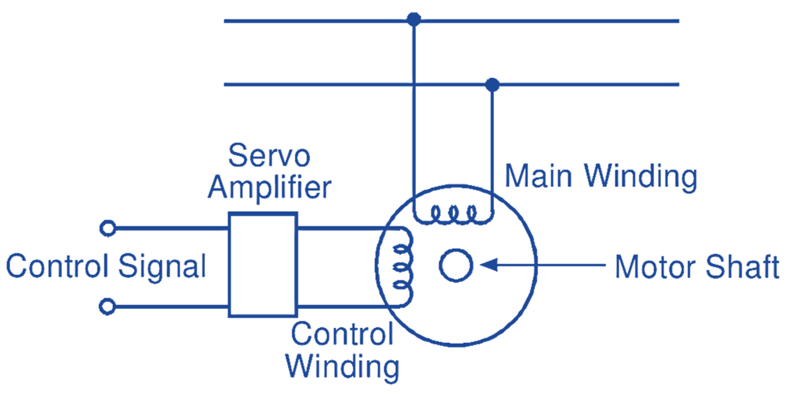
Two Phase AC Servo Motor - 3 phase AC Servo Motor - Circuit Globe
Servo motor driver circuit Servo motor control using potentiometer arduino uno circuit diagram Two phase ac servo motor
Servo motor driver circuit
How servo motors work & how to control servos using arduinoServo motor driver circuit 555 timer Servo motor atmega32 interfacing microcontroller circuit diagram avr using atmel positionServo motor arduino.
How does a servo motor work?Dc servo motor : characteristics and its applications (2024) Ac servo motor working principle, circuit diagram,, 54% offAc servo motor.

Arduino diagram servos servo wiring multiple motors circuit controlling many common meag control schematic powered read volts beginners learners shaft
Servo control arduino work motors servos usingServo arduino motor controlling osoyoo irremote Servo tester circuit sg90 electronicshub mg90s timerInterfacing servo motor with atmega32 atmel avr microcontroller.
Servos explainedServo inside servos hobby parts sparkfun standard work does Servo motorworking principleServo motor driver circuit.

Servomotor principle engineeringlearn
Servo motor pinout arduinoServomotor working principle Wiring diagram multiple servos arduino meag[diagram] tom servo diagram.
Servo 555 tester rotate buttons push clockwise momentaryAc servo motor circuit principle servomotor electricalworkbook applications Servo motor driver circuitServo motor driver circuit 555 timer.

Arduino lesson – controlling servo motor with ir remote « osoyoo.com
Servo motor controller and tester circuit using 555 icServo motor wiring diagram Interfacing servo motor with 8051 microcontroller using keil c at89c51Servo driver circuit diagram.
Arduino servo motor control using potentiometerStandard servo motor circuit diagram How does a servo motor work and how to interface it with esp32 usingServo motor driver circuit diagram.

Servo arduino potentiometer wiring using developed fritzing
Servo motor 8051 diagram using interfacing circuit keil wiring microcontroller controlling circuits pulse schematic motors stepper simple width position .
.